Fluid-bed cooler control system
Unlock the full potential of your fluid-bed cooler
Temperature-resistant process
Correct addition of moisture to cold and warm sands
Good access
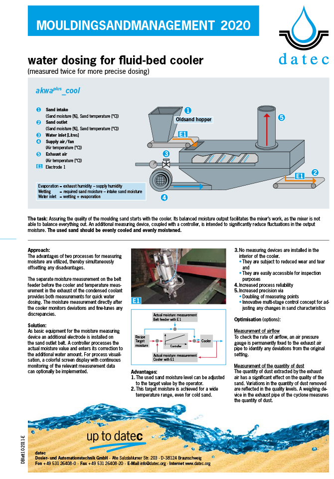
No measurement devices inside the mixer: Low levels of wear & simpler inspection
Data gathering via the ethernet
Comprehensive logging of the measurement data
Cleaner solution
Self-cleaning moisture electrodes
![]()

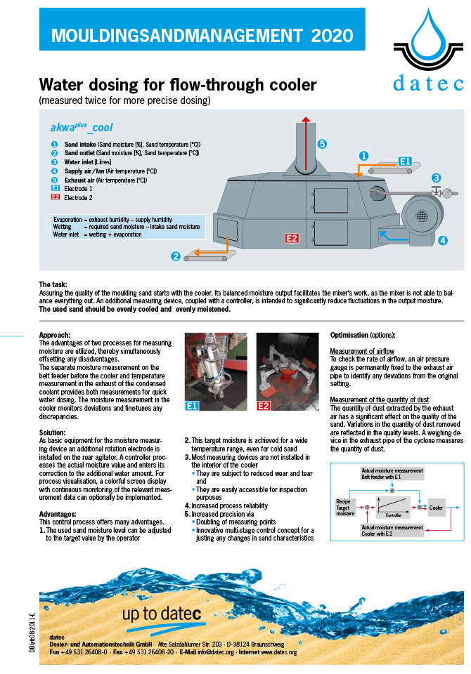
Task
Controls for a fluid-bed cooler must fulfil two core tasks:
• Sequential control for operating the cooler
• Water dosing for cooling and sand moistening to a target value
For a fluid-bed cooler, the incoming flow of sand must be carefully managed to avoid faults caused by the through-flow sieve becoming blocked.
Approach
In the cooler, the thermal energy is extracted from the reclaimed sand by evaporating water. Integrated water dosing ensures the correct quantity of water for cooling and that the target moisture value is achieved. The control system ensures an even flow of sand out of the pre-bunker and authorises the addition of water, the air supply and extraction. The control system also monitors the assembly units for correct functioning.
Solution
The quality of the cooling and sand wetting is determined by the project drawings for the cooler machine. Incorrect project drawing calculations cannot be rectified by the control system.
The cooler assembly is a sub-assembly in the used sand assembly. The sub-assembly which transports sand from the shake-out station to the moulding plant is not part of this. The system interface is the full and empty indicator in the pre-bunker of the cooler and ends at the outward conveyor belt. Evacuation is not an essential component in a cooler assembly for the used sand bunker.
A core task for control is an even incoming supply of sand which starts once the full indicator is reached and which is stopped again when the empty indicator becomes active. Depending on the equipment status, the air supply and extraction must be controlled in parallel.
If required, a power unit for the controlled units can also be supplied with hand controls. A means of visualisation to represent all operational statuses as well as assigned measurement and control values is included.
In addition to the continuous measurement display, relevant target, measurement and control data are gathered 1000 times per hour and documented in a file. If required, these documented values can be used retrospectively for detailed evaluations.
![]()